

Main Unit V3
The Main Unit V3, sold as the Zora-3 Server, is the unit Zora runs on. It clips onto a DIN rail, and expansion modules clip on beside it to add ports. The SSD module always sits next to it and comes with it.
To install it, follow Main Unit V3. This page is the reference for its connectors and modules.
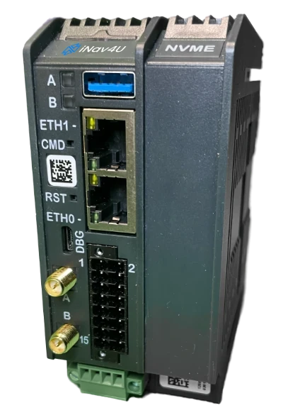
Front
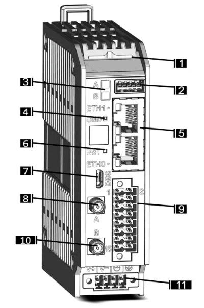
| No. | Part |
|---|---|
| 1 | System status LED, blue and amber. See Status LED |
| 2 | USB 3.0 port |
| 3 | LED A and LED B |
| 4 | Recessed push-button |
| 5 | Two Ethernet ports. ETH0 goes to the boat's router, ETH1 is the radar port (see RayNet radar) |
| 6 | Reset button |
| 7 | Console port (micro-USB), for servicing |
| 8 | Antenna A |
| 9 | Industrial I/O terminal block, 16 pins. See Industrial I/O |
| 10 | Antenna B |
| 11 | Power input. See Power |
The antenna connectors are used only on a unit ordered with the cellular modem, which is available on request. You do not need to fit antennas.
Right side
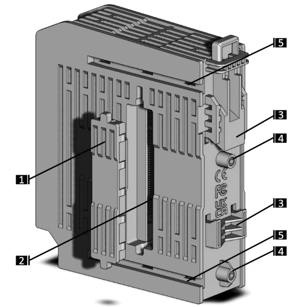
| No. | Part |
|---|---|
| 1 | Protective cover over the expansion connector |
| 2 | Expansion connector, where the first module plugs in |
| 3 | DIN-rail latch |
| 4 | M3 threads, for mounting without a DIN rail |
| 5 | Rails for the clamps that hold the modules together |
Power
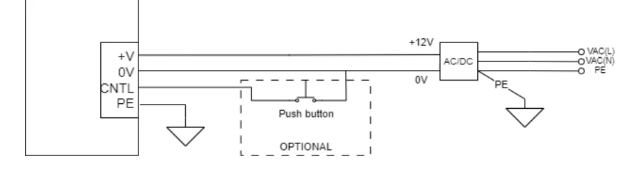
The main unit runs on 12 V or 24 V DC. It accepts 9.6 V to 28.8 V and draws 2.5 W to 8 W, depending on load and on the modules fitted. It is protected against reverse polarity. Never go above 32 V.
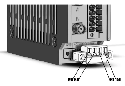
| Pin | Signal | Connect |
|---|---|---|
| 1 | +V | Positive supply (16 to 20 AWG) |
| 2 | V- | Negative supply (16 to 20 AWG) |
| 3 | CNTL | Only a remote power button. See below |
| 4 | P.E. | Protective earth, if the boat has one |
The green 4-pin plug comes in the box. It has screw terminals at 3.5 mm pitch and a screw flange that locks it in place.
The main unit starts as soon as power is connected.
Remote power button
You can fit a push-button (normally open) between CNTL (pin 3) and V- (pin 2):
| Main unit is | Press | Result |
|---|---|---|
| On | Short | Shuts down cleanly |
| On | Long | Forced power off |
| Off | Short | Starts |
DANGER
Never connect CNTL to a voltage. It may only be connected to V- through the button. Voltage on this pin can damage the main unit.
Status LED
| LED | Means |
|---|---|
| Off | Off, or in deep sleep |
| Solid blue | Starting up |
| Solid purple | The start-up software is damaged. Contact support |
| Blinking blue | Running normally |
| Blinking amber | The combination of expansion modules is not valid. See Module rules |
Industrial I/O
The 16-pin terminal block carries the main unit's own NMEA 2000, NMEA 0183 and digital I/O connections. Each of the four groups is isolated from the main unit and from the others. The push-in spring plug comes in the box and takes 16 to 26 AWG wire.
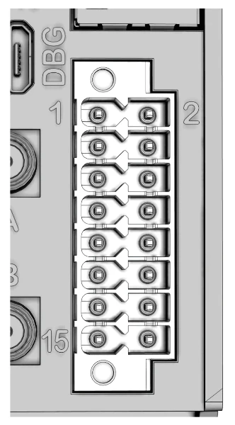
| Pin | Group | Signal |
|---|---|---|
| 1 | Digital I/O | Supply for the outputs (DIO_VIN) |
| 2 | Digital I/O | Input 0 |
| 3 | Digital I/O | Output 0 |
| 4 | Digital I/O | Input 1 |
| 5 | Digital I/O | Output 1 |
| 6 | Digital I/O | Ground (DIO_COM) |
| 7 | RS-485 | D- (negative) |
| 8 | RS-485 | D+ (positive) |
| 9 | RS-485 | Termination |
| 10 | RS-485 | Ground (RS485_COM) |
| 11 | RS-232 | RX, data into the main unit |
| 12 | RS-232 | TX, data out of the main unit |
| 13 | NMEA 2000 | Ground, black |
| 14 | RS-232 | Ground (RS232_COM) |
| 15 | NMEA 2000 | CAN low, blue |
| 16 | NMEA 2000 | CAN high, white |
In the Setup app these show on the Connections screen as NMEA 2000 / CAN Bus, RS485 / Modbus, RS232 / NMEA 0183 and Digital I/O, beside Network / TCP / UDP for the Ethernet ports. See NMEA 2000, NMEA 0183 and Digital I/O for setting each one up.
NMEA 2000
Connect the backbone drop to pins 16 (white, CAN high), 15 (blue, CAN low) and 13 (black, ground). The red power wire of the drop cable is not connected here.
The main unit has no termination resistor on this port. Terminate the backbone at both of its ends as usual.
For more NMEA 2000 ports, add the NMEA 2000 module.
NMEA 0183
The main unit has one RS-232 port and one RS-485 port for NMEA 0183.
- RS-232, for a device whose connections read TX, RX, OUT, IN, GND, COM or SG: its output (TX, OUT) to pin 11, its input (RX, IN) to pin 12 if Zora is to send to it, and its ground to pin 14.
- RS-485, for a device with a wire pair marked A/B, D+/D-, DATA+/DATA-, TX+/TX- or NMEA+/NMEA-: the positive wire to pin 8, the negative to pin 7, and its ground to pin 10. If the main unit is at the end of the line, bridge pin 9 to pin 10 to switch on the built-in 120 Ω termination.
If you are not sure which your device has, start with RS-232. If no data arrives, or it arrives garbled, wire it as RS-485. See Which port.
The RS-232 port runs at up to 250 kbit/s and the RS-485 port at up to 3 Mbit/s.
Digital I/O
Two digital inputs and two digital outputs, for 24 V control circuits (EN 61131-2). The inputs need no supply. The outputs need an external supply of 6 V to 30 V on pin 1, and switch up to 1 A each.
In the box
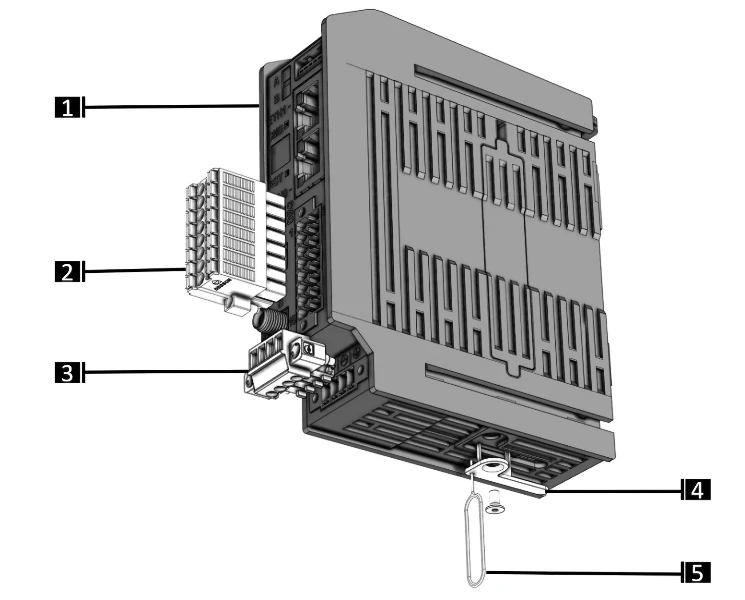
| No. | Part | Quantity |
|---|---|---|
| 1 | Main unit | 1 |
| 2 | 16-pin plug for the industrial I/O block (black) | 1 |
| 3 | 4-pin power plug (green) | 1 |
Parts 4 and 5 in the picture are not included.
Mounting
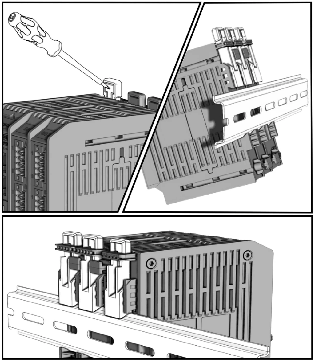
To fit the main unit and its modules on a DIN rail (EN 50022):
- Check that the main unit and every module has its DIN latch, and that the modules are held together with the top and bottom clamps.
- Raise all the latches. A screwdriver tip pushed on the lever lifts a latch.
- Place the assembly on the rail, hooking the bottom teeth on first.
- Check it sits straight on the rail, then push every latch down until it clicks.
To take it off, raise all the latches and lift the assembly off, top teeth first.
WARNING
Never leave the assembly on the rail with its latches open, and never pull it by its cables. Leave 50 mm free above and below it for cooling, and put nothing on top of it.
Expansion modules
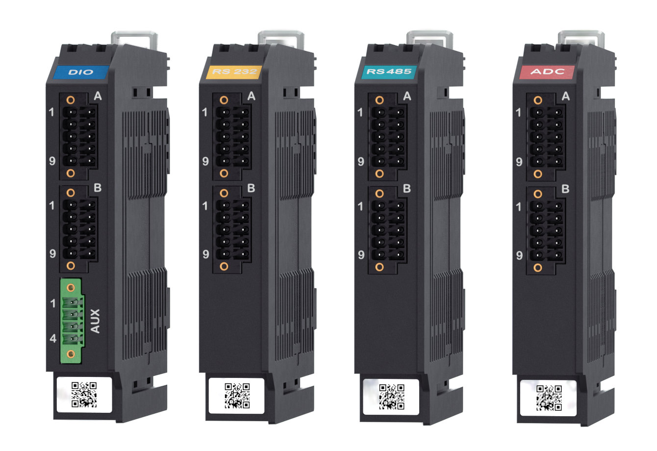
Modules clip on to the right of the main unit, each one plugging into the one before it. They take their power from the main unit, except where a module's own section says otherwise. Each module is 110 x 20 x 95 mm, weighs 110 g and runs from -30 °C to 70 °C.
On the Setup app's Connections screen, the Hardware tab shows the modules the main unit found. See The Connections screen.
| Module | Shows in Setup as | Adds |
|---|---|---|
| SSD | NVMe | The data disk. Comes with the main unit |
| NMEA 2000 | NMEA2000 | 2 NMEA 2000 ports, 4 digital inputs, 4 digital outputs |
| RS-485 | RS485 | 4 RS-485 ports |
| RS-232 | RS232 | 4 RS-232 ports |
| Digital I/O | Digital IO | 8 digital inputs, 8 digital outputs |
| Analog input | Analog Input | 8 analog inputs |
| Wireless mesh | Wireless Mesh | Bluetooth mesh, Thread and Zigbee radio |
Module rules
- The SSD module always goes first, directly beside the main unit.
- One main unit takes up to eight modules, the SSD module included.
- At most one NMEA 2000 module, one analog input module and four digital I/O modules.
- At most three RS-485 and RS-232 modules together.
- The NMEA 2000 module and the analog input module cannot be fitted together.
With a combination the main unit does not accept, its status LED blinks amber.
SSD module
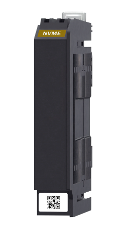
A 256 GB NVMe SSD. It holds the charts, the logbook, the documents and the settings. The main unit starts without it, but Zora does not: every screen shows No data volume until the disk is back. Fit it before you install the main unit; see Connect the SSD module.
NMEA 2000 module
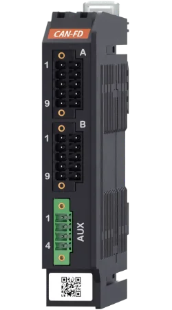
Two more NMEA 2000 ports, each isolated, plus four digital inputs and four digital outputs. In the Setup app its ports show as NMEA 2000 / CAN Bus (1) and (2). Each port can go to a separate backbone.
Connector A, NMEA 2000
| Pin | Port 0 | Pin | Port 1 |
|---|---|---|---|
| 1 | CAN low, blue | 9 | CAN low, blue |
| 2 | CAN high, white | 10 | CAN high, white |
| 3 + 4 | Bridge for 120 Ω termination | 7 + 8 | Bridge for 120 Ω termination |
| 5 or 6 | Ground, black | 5 or 6 | Ground, black |
Bridge the termination pins only on a port at the end of its backbone. The red power wire of the drop cable is not connected: the module is powered by the main unit.
Connector B, digital I/O: inputs 0 to 3 on pins 1 to 4, ground on pins 5 and 6, outputs 0 to 3 on pins 7 to 10.
AUX, supply for the digital I/O: 1 input ground, 2 input supply, 3 output ground, 4 output supply. The digital I/O block works only with a supply on AUX, isolated from the main unit.
Not built
Zora does not use this module's digital inputs and outputs yet. Its two NMEA 2000 ports work.
RS-485 module
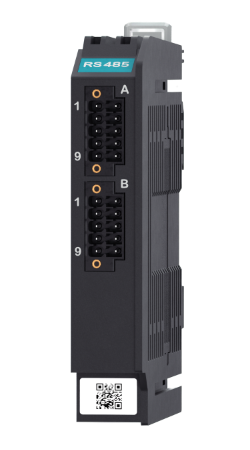
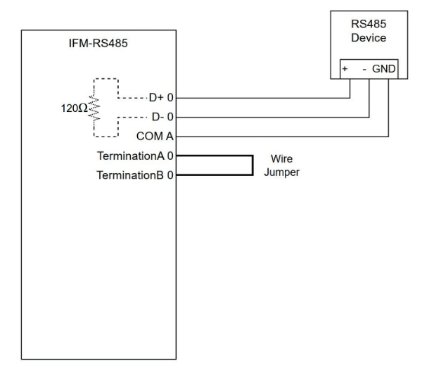
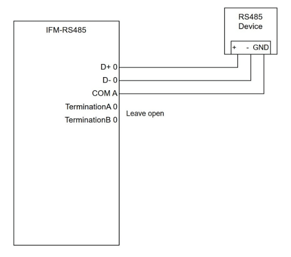
Four RS-485 ports for NMEA 0183 or Modbus, up to 4 Mbit/s. Ports 0 and 1 (connector A) and ports 2 and 3 (connector B) are two blocks, isolated from each other and from the main unit. In the Setup app they show as RS485 / Modbus (1) to (4).
| Device wire | Port 0 | Port 1 | Port 2 | Port 3 |
|---|---|---|---|---|
| Connector A | Connector A | Connector B | Connector B | |
| D+ (NMEA+, A, TX+) | 2 | 10 | 2 | 10 |
| D- (NMEA-, B, TX-) | 1 | 9 | 1 | 9 |
| Ground or shield | 5 or 6 | 5 or 6 | 5 or 6 | 5 or 6 |
| 120 Ω termination, only at the end of the line | bridge 3 + 4 | bridge 7 + 8 | bridge 3 + 4 | bridge 7 + 8 |
Connector A's ground and connector B's ground are isolated from each other. Do not join them.
RS-232 module
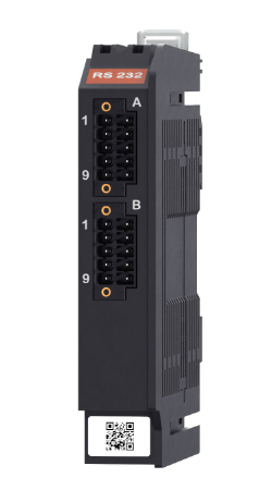
Four RS-232 ports (RX and TX) for NMEA 0183, up to 250 kbit/s. Ports 0 and 1 (connector A) and ports 2 and 3 (connector B) are two blocks, isolated from each other and from the main unit. In the Setup app they show as RS232 / NMEA 0183 (1) to (4).
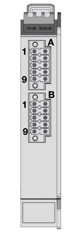
| Pin | Connector A | Connector B |
|---|---|---|
| 1 | Port 0 RX, data in | Port 2 RX, data in |
| 2 | Port 0 TX, data out | Port 2 TX, data out |
| 3, 4, 7, 8 | Ground, ports 0 and 1 | Ground, ports 2 and 3 |
| 5, 6 | Not connected | Not connected |
| 9 | Port 1 RX, data in | Port 3 RX, data in |
| 10 | Port 1 TX, data out | Port 3 TX, data out |
Digital I/O module
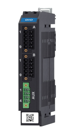
Eight digital inputs and eight digital outputs, for 24 V control circuits (EN 61131-2), each block isolated. Each block needs its own external supply on AUX: 10 V to 30 V for the inputs, 10.5 V to 36 V for the outputs. An output switches up to 1 A.
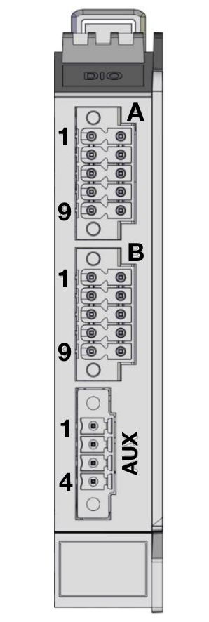
| Pin | Connector A, inputs | Connector B, outputs | AUX, supply |
|---|---|---|---|
| 1 to 4 | Inputs 0 to 3 | Outputs 0 to 3 | 1 input ground, 2 input supply, 3 output ground, 4 output supply |
| 5, 6 | Input ground | Output ground | |
| 7 to 10 | Inputs 4 to 7 | Outputs 4 to 7 |
Not built
Zora shows this module on the Hardware tab but does not read or switch its inputs and outputs yet.
Analog input module
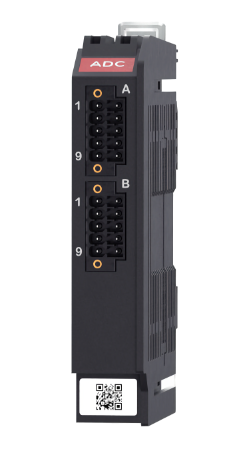
Eight analog inputs in two blocks of four (connector A: inputs 0 to 3, connector B: inputs 4 to 7), for sensors that give 0 V to 10 V or 4 mA to 20 mA. Each block is set with a wire: bridge pin 9 (COM) to pin 10 (MODE) for 4 mA to 20 mA, or leave pin 10 open for 0 V to 10 V. The inputs are on pins 2, 4, 6 and 8, each with its ground on the pin before it.
Not built
Zora shows this module on the Hardware tab but does not read its inputs yet.
Wireless mesh module
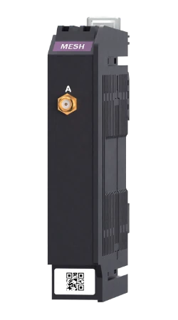
A radio for Bluetooth mesh, Thread and Zigbee devices, with one antenna connector.
Not built
Zora shows this module on the Hardware tab but does not use it yet.
Specifications
| Processor | Quad-core ARM, 1.8 GHz |
| Memory | 8 GB RAM, 64 GB built-in storage |
| Data disk | SSD module, 256 GB |
| Network | 2 Gigabit Ethernet ports |
| Ports | 1 USB 3.0, 1 NMEA 2000, 1 RS-485, 1 RS-232, 2 digital inputs, 2 digital outputs |
| Cellular modem | On request |
| Security | Secure boot, TPM 2.0 |
| Supply | 12 V to 24 V DC (9.6 V to 28.8 V), reverse polarity protected |
| Consumption | 2.5 W to 8 W |
| Size | Main unit 110 x 30 x 95 mm, each module 110 x 20 x 95 mm |
| Weight | Main unit 0.22 kg, each module 0.11 kg |
| Housing | DIN rail (EN 50022), ABS/PC, fanless |
| Operating temperature | 0 °C to 50 °C, or -40 °C to 70 °C for the industrial version |
| Storage temperature | -40 °C to 85 °C |
| Humidity | 10% to 90% operating, 5% to 95% stored |
| Approvals | FCC, CE, UKCA. EMC EN 55032/5, EN 61000-6-2, EN 61000-6-3. Safety EN/UL/IEC 62368-1 |