

Main Unit V3
The Main Unit V3 is the server that runs Zora, with its SSD module and any I/O modules stacked beside it on a DIN rail. This page takes it from the box to a unit that is powered, on the boat's network and ready to be claimed. Connector pinouts and specifications are in the Main Unit V3 hardware reference.
Before you start
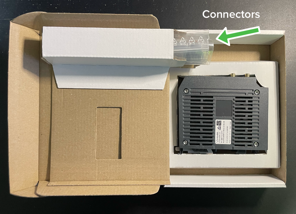
The mating connectors for the power input and the I/O terminal block come in the box.
The boat's router needs a working internet connection when you claim the unit. Claiming it is what makes iNav4U install Zora on it, and that install comes over the internet.
Stack the modules
Disconnect all power from the server before you attach or remove any module.
The server is always the left-most unit. Stack the SSD module next to it, then any other modules to the right of that. An assembly takes up to eight modules, the SSD module included, and within that:
| Module | Most per assembly |
|---|---|
| RS-485 and RS-232, together | 3 |
| Digital I/O | 4 |
| Analog input | 1 |
| Wireless | 1 |
To attach a module:
- Remove the silicone plug from the StackLink opening where the two units meet. Keep it.
- Line the StackLink bridge up with the opening.
- Push them straight together until you hear a soft click and no gap is left.
- Push the secure clamps into the top and bottom clamp rails at the back until they are seated.
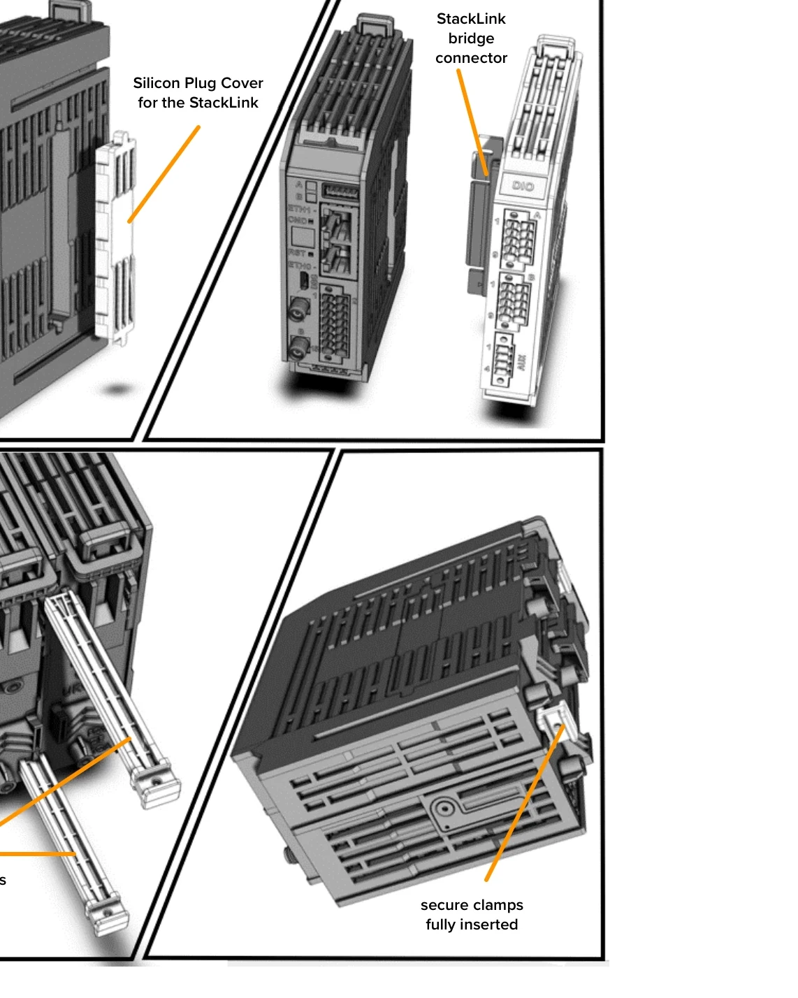
To remove one, lever each clamp out with a thin screwdriver in its handle, pull the modules straight apart, and put the silicone plug back over the opening that is left. The bridge stays on the right-hand module.
Mount it
Clamp every module together before it goes on the rail. Raise the DIN latches, seat the bottom teeth on the rail first, then push the latches down until each one clicks. Leave 50 mm of air above and below the assembly.
Connect NMEA 2000
Wire the backbone to the CAN pins of the I/O terminal block; the hardware reference has the pinout. The server has no CAN termination of its own, so the backbone needs its own terminators.
Connect the router
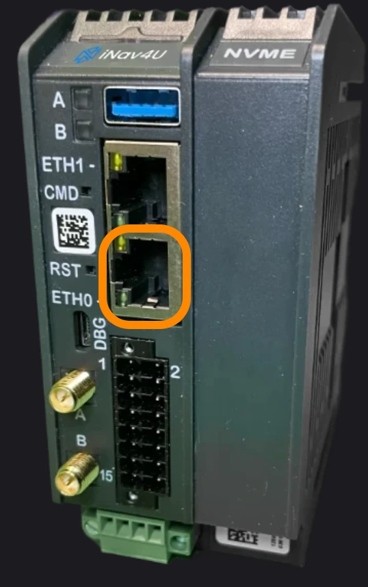
Run an Ethernet cable from the ETH0 port to a LAN port on the boat's router. ETH0 is the lower of the two ports. ETH1, the upper one, is the radar port; see RayNet radar.
Connect power
Supply 12 to 24 V DC. The server runs from 9.6 to 28.8 V. On the power connector, pin 1 is V+, pin 2 is V− and pin 4 is protective earth.
Pin 3, CNTL, is for an optional remote power button wired between CNTL and V−. Never connect CNTL to a DC voltage.
There is no power switch. The server starts as soon as power is applied, and its status LED blinks blue once it is running. A blinking amber LED means the modules are in a combination the server does not accept: power down and check the stacking rules above.
Claim it and open Zora
- Create the owner's cloud account and claim the device. iNav4U then installs Zora on the unit over the boat's internet connection.
- Open Zora from a laptop or tablet on the boat's network.
- On a new boat, Zora opens the first-install assistant.
- Reserve the unit's address in the router, so it never changes: Keep the address the same.
If it does not work
| What you see | What to check |
|---|---|
| Zora shows No data volume | The SSD module is not reached. Power down, check it sits against the server and is clamped, then power up |
| Status LED blinks amber | The modules are in a combination the server does not accept. Check Stack the modules |